This tutorial is about understanding how LDR Works. A Light Dependent Resistor (LDR) is also called a photo resistor or a cadmium sulfide (CdS) cell. It is also called a photoconductor. It is basically a photocell that works on the principle of photoconductivity. The passive component is basically a resistor whose resistance value decreases when the intensity of light decreases.
The resistor behaves as per amount of light and its output directly varies with it. In general, LDR resistance is minimum (ideally zero) when it receives maximum amount of light and goes to maximum (ideally infinite) when there is no light falling on it. The resistance is very high in darkness, almost high as 1MΩ but when there is light that falls on the LDR, the resistance is falling down to a few KΩ (depending on the model.
Light dependent resistors come in different shapes and colors. LDRs are very useful in many electronic circuits, especially in alarms, switching devices, clocks, street lights and more. There are some audio application uses such as audio limiters or compressors. It is used to turn ON or OFF a device according to the ambient light.
The vast majority of LDRs are made from cadmium-sulphide (CdS), and they are very cheap, but also not very accurate. They are very good for detecting changes in light levels and determining if it is ‘dark’ or ‘light’, but without individual calibration they not suitable for accurately measuring light levels.
How Does a CdS Photocell Work
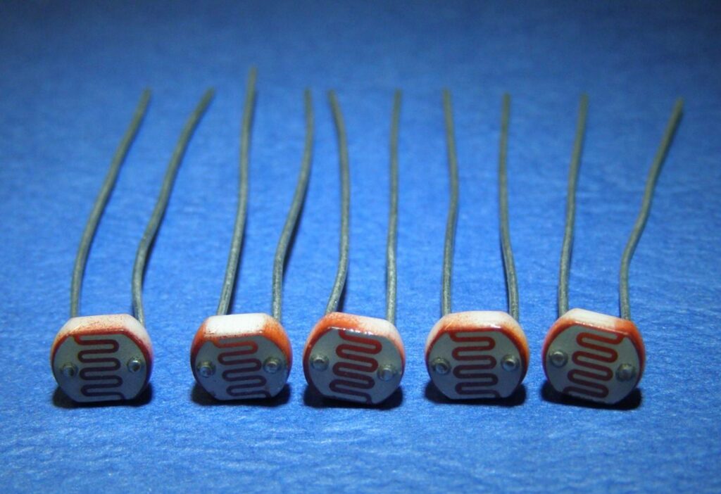
Pictured below is a typical light dependent resistor. It has two wire leads which terminate in the face of the light detector – the two metal dots you see are the ends of those electrodes. The main body of the light detector component is made of ceramic – an excellent insulator. On the face of the ceramic a thin strip of cadmium sulphide is coated in a zig-zag pattern (to maximise the length of the strip while keeping the component small) which is connected at each end to an electrode. The front face is then coated in clear plastic, epoxy, glass, or similar.

Cadmium-sulphide is a high resistance semiconductor, and is chosen for light detectors as it gives the same spectral response as the human eye – i.e. it ‘sees’/responds to the same range of wavelengths of light that we can see. Specifically, cadmium-sulphide is a photoconductive material. That means that photons of light hitting it with sufficient energy will release electrons from their atomic bonds.
When a negatively charged electron is freed by a photon of light, it leaves behind a positively charged ‘hole’. When a voltage is applied across the two wire leads of the light detector, the free electron moves one way along the CdS strip, and the free ‘hole’ moves the other way; and it is this movement of charge which is electricity flowing through the light detector. The higher the light intensity, the more photons of light are hitting the CdS strip, the more electron-hole pairs are generated, the more electricity can flow through the light detector, and so the lower the resistance of the light detector (i.e. it is easier for electricity to flow through the light detector when the light intensity hitting it is high).
How LDR works
It is relatively easy to understand the basics of how an LDR works without delving into complicated explanations. It is first necessary to understand that an electrical current consists of the movement of electrons within a material. Good conductors have a large number of free electrons that can drift in a given direction under the action of a potential difference. Insulators with a high resistance have very few free electrons, and therefore it is hard to make the them move and hence a current to flow.
An LDR or photo resistor is made using semiconductor material with a high resistance. It has a high resistance because there are very few electrons that are free and able to move – the vast majority of the electrons are locked into the crystal lattice and unable to move. Therefore in this state there is a high LDR resistance.
You need to take into considerations about the size of LDR because it’ll affect how its placed on PCB. The foot print of LDR are different based on size. In order to place LDR on PCB, the dimensions of LDR are important. If you don’t know about PCB Design, more about it can be read here
Now to answer the original question about how ldr works, here it is. As light falls on the semiconductor, the light photons are absorbed by the semiconductor lattice and some of their energy is transferred to the electrons. This gives some of them sufficient energy to break free from the crystal lattice so that they can then conduct electricity. This results in a lowering of the resistance of the semiconductor and hence the overall LDR resistance.The process is progressive, and as more light shines on the LDR semiconductor, so more electrons are released to conduct electricity and the resistance falls further.
I’ve tried to explain how ldr works in in the simplest language for complete beginners. If you want to deep dive into the technical details of LDR working, you can read so here and here you can see how to actually use it in a circuit


Can you recommend a waterproof, more industrial sensor that I can use instead of LDR?
Can you share what exactly you’re trying to build?